-
Tel: 86-577-62704999 Fax: 86-577-62691368
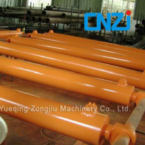
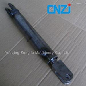
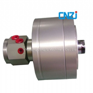
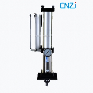
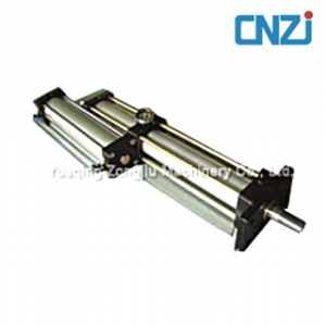
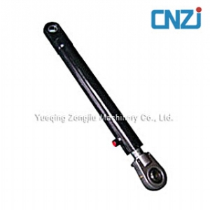
Compact hydraulic cylinder, specializing in hydraulic cylinders and pneumatic cylinders.

- Engineering hydraulic cylinder
- ISO international standard hydraulic cylinder
- Large hydraulic cylinder
- Coal mining cylinder
- Welded hydraulic cylinder
- Tie rod cylinder
- Telescopic cylinder
- Metallurgy cylinder
- Standard pneumatic cylinder(WITHOUT TIE ROD)
- Standard pneumatic cylinder (WITH TIE ROD)
- Standard pneumatic cylinder
- Stainless steel cylinder
- Aluminum alloy mini pneumatic cylinder
- Compact pneumatic cylinder
- Double rod pneumatic cylinder
- Oil buffer
- Valves
- 2W solenoid valve
- Hydraulic power unit
- Hydraulic cylinder
- Fishing tools

TeL: +86-577-62704999 62698557
Fax: +86-577-62691368
Mobile: +86-15888444185/13989760103
Contact Person: Mr.huang
Email: chinacnzj@chinacnzj.com
WebSite:http://www.hydro-cylinders.com
You Are Here: Home » Products » Hydraulic cylinder
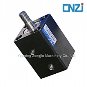
Compact hydraulic cylinder
|
160S-1/THS16 Bore | ||
|
SD |
General purpose type |
160S-1 6 SD Bore N Stroke T (ø20 - ø125) |
|
Cutting fluid proof type |
160SW-1 6 SD Bore N Stroke T (ø32 - ø100) | |
|
None : Female thread | ||
|
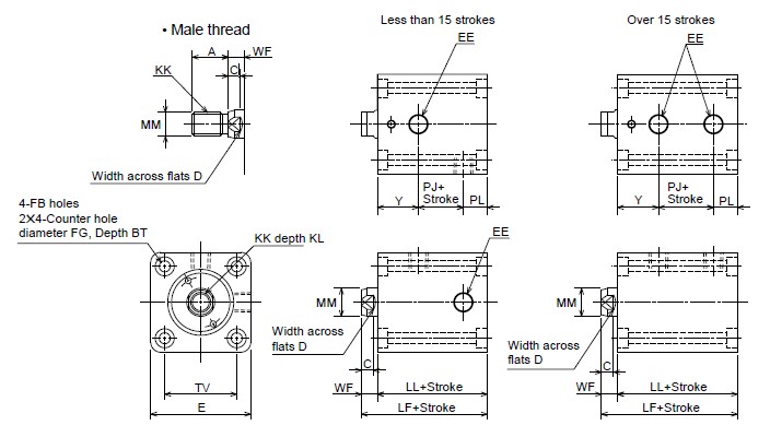
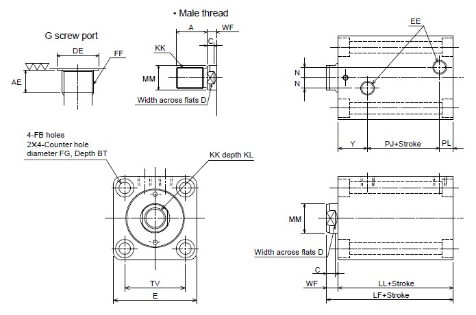
Symbol |
A |
AE |
BT |
C |
D |
DE |
E |
EE |
FB |
FF |
FG |
KK |
KL | |
|
Female thread |
Male thread | |||||||||||||
|
ø20 |
15(25) |
– |
5.4 |
6 |
10 |
– |
44 |
Rc1/8 |
ø5.5 |
– |
ø9.5 |
M8&< 0005;1.25 |
M10&< 0005;1.25 |
10 |
|
ø25 |
18(30) |
– |
5.4 |
6 |
12 |
– |
50 |
Rc1/8 |
ø5.5 |
– |
ø9.5 |
M10&< 0005;1.5 |
M12&< 0005;1.25 |
12 |
|
ø32 |
25(40) |
8 |
6.5 |
7 |
14 |
ø17.5 |
62 |
Rc1/4 |
ø6.6 |
G1/8 |
ø11 |
M12&< 0005;1.75 |
M16&< 0005;1.5 |
15 |
|
ø40 |
30(45) |
8 |
8.6 |
7 |
19 |
ø17.5 |
70 |
Rc1/4 |
ø9 |
G1/8 |
ø14 |
M16&< 0005;2 |
M20&< 0005;1.5 |
20 |
|
ø50 |
35(50) |
12 |
10.8 |
8 |
24 |
ø21.5 |
80 |
Rc1/4 |
ø11 |
G1/4 |
ø17.5 |
M20&< 0005;2.5 |
M24&< 0005;1.5 |
24 |
|
ø63 |
45(60) |
12 |
13 |
9 |
30 |
ø21.5 |
94 |
Rc1/4 |
ø14 |
G1/4 |
ø20 |
M27&< 0005;3 |
M30&< 0005;1.5 |
33 |
|
ø80 |
60(80) |
12 |
15.2 |
14 |
41 |
ø21.5 |
114 |
Rc3/8 |
ø16 |
G1/4 |
ø23 |
M30&< 0005;3.5 |
M39&< 0005;1.5 |
36 |
|
ø100 |
75(95) |
12 |
19.5 |
22 |
50 |
ø25.5 |
140 |
Rc3/8 |
ø20 |
G3/8 |
ø29 |
M39&< 0005;4 |
M48&< 0005;1.5 |
45 |
|
ø125 |
95(125) |
14 |
23.5 |
25 |
65 |
ø30 |
172 |
Rc1/2 |
ø24 |
G1/2 |
ø35 |
M48&< 0005;5 |
M64&< 0005;2 |
58 |
|
Symbol |
LF |
LL |
MM |
N |
PJ |
PL |
TV |
WF |
Y | ||||
|
Rc thread |
G thread |
Rc thread |
G thread |
Rc thread |
G thread |
Rc thread |
G thread | ||||||
|
ø20 |
51 |
43 |
ø12 |
– |
– |
10.5 |
– |
12 |
– |
30 |
8 |
20.5 |
– |
|
ø25 |
53 |
45 |
ø14 |
– |
– |
12.5 |
– |
12 |
– |
36 |
8 |
20.5 |
– |
|
ø32 |
64 |
54 |
ø18 |
10 |
10 |
14 |
14 |
12 |
12 |
47 |
10 |
28 |
28 |
|
ø40 |
65 |
55 |
ø22 |
10 |
10 |
16 |
16 |
12 |
12 |
52 |
10 |
27 |
27 |
|
ø50 |
71 |
60 |
ø28 |
10 |
14 |
19 |
13.5 |
13 |
18.5 |
58 |
11 |
28 |
28 |
|
ø63 |
80 |
67 |
ø36 |
10 |
16 |
24 |
20 |
13 |
17 |
69 |
13 |
30 |
30 |
|
ø80 |
95 |
78 |
ø45 |
15 |
19 |
25 |
24 |
18 |
18 |
86 |
17 |
35 |
36 |
|
ø100 |
122 |
96 |
ø56 |
15 |
18 |
26 |
26 |
28 |
28 |
106 |
26 |
42 |
42 |
&S226;The lock nut needs to be ordered separately.
&S226;20mm and 25mm bore size of Cutting Fluid Proof Type are not available.
&S226;Allowance of MM is f8.
|
ST |
General purpose type |
160S-1 6 ST Bore N Stroke T (ø32 -ø80/Made-to-order) |
|
None : Female thread | ||
|
over 101 strokes (110,120,130,140,150,160,170,180,190,200? | ||
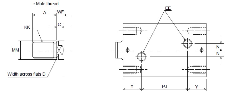
|
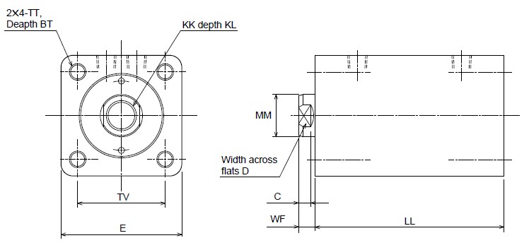
Symbol |
A |
BT |
C |
D |
E |
EE |
KK |
MM |
N |
TT |
TV |
WF |
Y | |
|
Female thread |
Male thread | |||||||||||||
|
ø32 |
25(40) |
15 |
7 |
14 |
62 |
Rc1/4 |
M12&<0005;1.75 |
M16&<0005;1.5 |
ø18 |
10 |
M6&<0005;1 |
47 |
10 |
28 |
|
ø40 |
30(45) |
20 |
7 |
19 |
70 |
Rc1/4 |
M16&<0005;2 |
M20&<0005;1.5 |
ø22 |
10 |
M8&<0005;1.25 |
52 |
10 |
27 |
|
ø50 |
35(50) |
25 |
8 |
24 |
80 |
Rc1/4 |
M20&<0005;2.5 |
M24&<0005;1.5 |
ø28 |
10 |
M10&<0005;1.5 |
58 |
11 |
28 |
|
ø63 |
45(60) |
30 |
9 |
30 |
94 |
Rc1/4 |
M27&<0005;3 |
M30&<0005;1.5 |
ø36 |
10 |
M12&<0005;1.75 |
69 |
13 |
30 |
|
ø80 |
60(80) |
35 |
14 |
41 |
114 |
Rc3/8 |
M30&<0005;3.5 |
M39&<0005;1.5 |
ø45 |
15 |
M16&<0005;2 |
86 |
17 |
35 |
|
Symbol |
LL |
PJ | ||||||||||||||||||
|
110 |
120 |
130 |
140 |
150 |
160 |
170 |
180 |
190 |
200 |
110 |
120 |
130 |
140 |
150 |
160 |
170 |
180 |
190 |
200 | |
|
ø32 |
192 |
202 |
212 |
222 |
232 |
242 |
252 |
262 |
272 |
282 |
136 |
146 |
156 |
166 |
176 |
186 |
196 |
206 |
216 |
226 |
|
ø40 |
192 |
202 |
212 |
222 |
232 |
242 |
252 |
262 |
272 |
282 |
138 |
148 |
158 |
168 |
178 |
188 |
198 |
208 |
218 |
228 |
|
ø50 |
195 |
205 |
215 |
225 |
235 |
245 |
255 |
265 |
275 |
285 |
139 |
149 |
159 |
169 |
179 |
189 |
199 |
209 |
219 |
229 |
|
ø63 |
202 |
212 |
222 |
232 |
242 |
252 |
262 |
272 |
282 |
292 |
142 |
152 |
162 |
272 |
182 |
192 |
202 |
212 |
222 |
232 |
|
ø80 |
215 |
225 |
235 |
245 |
255 |
265 |
275 |
285 |
295 |
305 |
145 |
155 |
165 |
175 |
185 |
195 |
205 |
215 |
225 |
235 |
&S226; The lock nut needs to be ordered separately.
&S226; Allowance of MM is f8.
|
160S-1/THS16 Bore | |
|
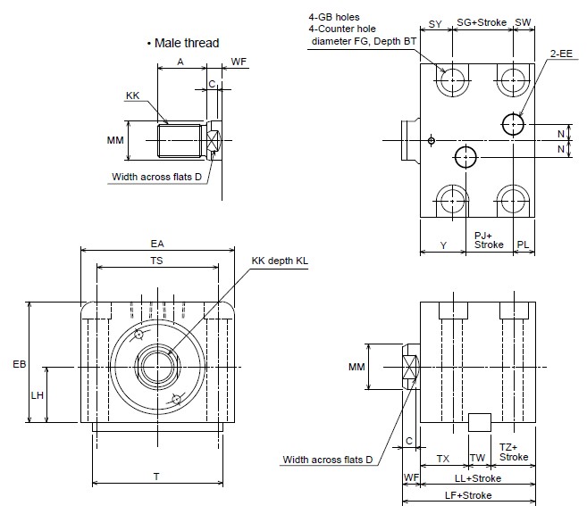
LA |
General purpose type160S-1 6 LA Bore N Stroke T (ø32 -ø63) |
|
None : Female thread | |
|
Symbol |
A |
BT |
C |
D |
EA |
EB |
EE |
FG |
GB |
KK |
KL |
LF |
LH | |
|
Female thread |
Male thread | |||||||||||||
|
ø32 |
25(40) |
8.6 |
7 |
14 |
70 |
56 |
Rc1/4 |
ø14 |
ø9 |
M12&<0005;1.75 |
M16&<0005;1.5 |
15 |
64 |
25±0.06 |
|
ø40 |
30(45) |
10.8 |
7 |
19 |
80 |
64 |
Rc1/4 |
ø17.5 |
ø11 |
M16&<0005;2 |
M20&<0005;1.5 |
20 |
65 |
29±0.06 |
|
ø50 |
35(50) |
13 |
8 |
24 |
94 |
74 |
Rc1/4 |
ø20 |
ø14 |
M20&<0005;2.5 |
M24&<0005;1.5 |
24 |
71 |
34±0.06 |
|
ø63 |
45(60) |
15.2 |
9 |
30 |
114 |
89 |
Rc1/4 |
ø23 |
ø16 |
M27&<0005;3 |
M30&<0005;1.5 |
33 |
80 |
42±0.06 |
|
Symbol |
LL |
MM |
N |
PJ |
PL |
SG |
SW |
SY |
T |
TS |
TW |
TX |
TZ |
WF |
Y |
|
ø32 |
54 |
ø18 |
10 |
14 |
12 |
24 |
10 |
20 |
63 |
56 |
12 |
28 |
14 |
10 |
28 |
|
ø40 |
55 |
ø22 |
10 |
16 |
12 |
23 |
12 |
20 |
70 |
62 |
12 |
28 |
15 |
10 |
27 |
|
ø50 |
60 |
ø28 |
10 |
19 |
13 |
27 |
13 |
20 |
80 |
74 |
14 |
29 |
17 |
11 |
28 |
|
ø63 |
67 |
ø36 |
10 |
24 |
13 |
32 |
15 |
20 |
100 |
90 |
16 |
31 |
20 |
13 |
30 |
&S226; The lock nut needs to be ordered separately.
&S226; Allowance of MM is f8.
|
Recommended Key Way Dimensions |
When using a parallel key: | |||||||||||||||||||||||||
 |
 | |||||||||||||||||||||||||
|
When not using a parallel key: | ||||||||||||||||||||||||||
 | ||||||||||||||||||||||||||
|
Dimension Table |
Use the same dimensions for the stopper as the attached parallel key. | |||||||||||||||||||||||||
|
&S226; When using the foot type, use the
attached parallel key to install the cylinder,
referring to the “Recommended Key Way
Dimensions.”
&S226; When not using the parallel key, attach the stoppers to the cylinder’s front
and rear sides toward its stroke direction.
If the cylinder is used without using the key
or stoppers, a large force is applied to the
cylinder’s mounting bolts, possibly resulting
in the fracturing of the bolts. | |||||||||||||||||||||||||